

In this article, we explore the technical background, details, and design challenges of one of the most critical components of conventional silicon solar cells: the busbar.
In doing so, we also address the currently hot topic of multi-busbar cells, looking at future trends and developments in solar cell design research and in this regard the future of the busbar.
What is a solar busbar and how does it work?
Conventional silicon solar cells are metalized with thin rectangular-shaped strips printed on the front and rear of a solar cell. These front and rear contact strips are referred to as busbars, or bus bars – the correct spelling is subject to nitpicking debates in the PV industry…
Solar busbars have one simple, yet significant purpose: they conduct the direct current produced by the solar cell from the incoming photons.
Commonly, solar cell busbars are made of copper plated with silver. The silver plating is necessary to improve current conductivity (front side) as well as to reduce oxidization (rear side).
Perpendicular to the busbars are the metallic and super-thin grid fingers, also called contact fingers or simply: fingers, which are connected by the busbar.
The fingers collect the generated current and deliver it to the busbars. Tab wires are soldered to the busbars to connect a string of cells and thus collect the electric current of one cell string.
Clusters of tab-wired cell strings are connected in parallel by bus wires which then deliver the cumulative power from all the cells to the junction box.
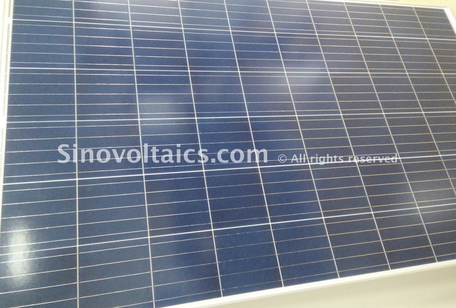
The below image illustrates a polycrystalline silicon PV cell with 3 busbars (horizontal) and fingers (vertical):
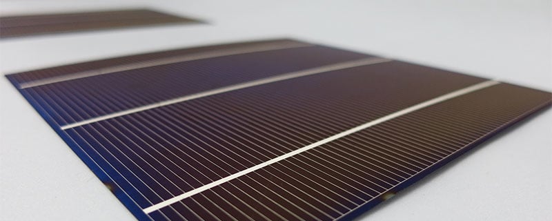
Polycrystalline silicon solar cell: busbars and fingers
Basically, the surface of a conventional solar cell is characterized by a grid of these fine, current-collecting and delivering fingers, and the current-conducting busbars. These contacts – the busbars and the fingers – are printed onto the surface via a technology called screen printing, a process that we introduced in an earlier article about solar cell production.
Key in conventional solar cell design and production is to strike an optimal balance between busbar and finger resistance losses and shading and reflection losses – the former caused by using too few metallic contacts, thus creating greater distances between them, and the latter being the consequence of too many contacts on the cell surface, basically preventing light from entering the solar cell.
Crucial parameters are in this regard the height and width of the busbars, the width of the fingers, the spaces between the fingers and the busbars as well as the metal type and quality.
Solar bus wire and tab wire: purpose and configuration
As individual solar junctions produce low voltage and in order to obtain suitable voltages, the solar cells have to be connected in series, forming rows.
To connect the individual cells in series and also to lower series resistance, a metal contact strip – the tab wire – is either manually or automatically soldered to the busbar. At the end of a cell string, the bus wire connects these rows in parallel.
Tab wire or tabbing wire is flat copper wire. It is normally prepared by rolling round copper wire into a flat shape. The copper core is given a solder coat by the manufacturer to allow easy soldering to the cells.
Various thicknesses and widths are available, from about 1 mm to about 2 mm. Thicknesses are from about one-tenth of a millimeter to about two-tenths of a millimeter.
The bus wire is used to connect these parallel busbar rows in parallel. It is also, like the tabbing wire, made of a flat cross-section. Since it has to carry a sum of the row currents, the bus wire has to have a larger thickness and width to allow less resistance per unit length than the tabbing wire.
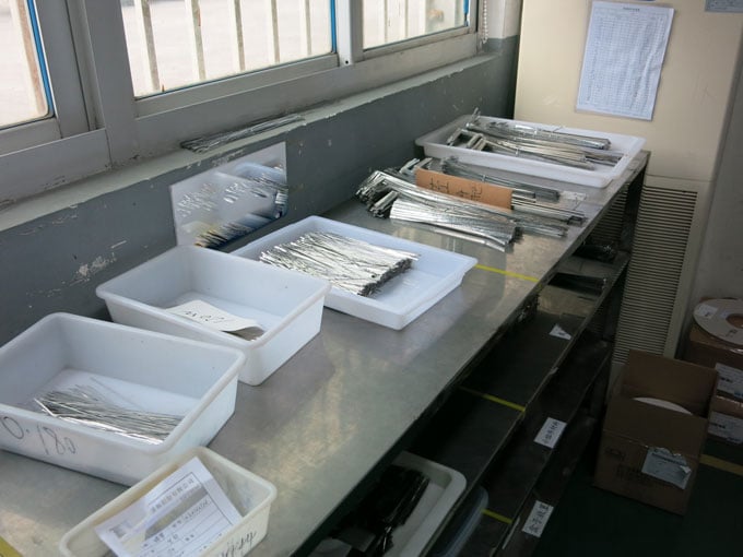
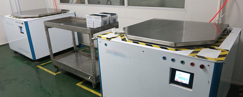
Material collection at a manufacturer: tab wires
Like tabbing wire, it is also made from round copper wire by a rolling process and is coated with a layer of solder to permit easy soldering.
Normally available thickness is from about 0.15 mm to about 0.35 mm. It is available in widths of about 4 mm to about 6 mm.
As a matter of fact, tabbing wire and bus wire for solar modules are generically the same. Only, the bus wire has to carry the bus current, which is many times larger than the row current. Hence the bus wire has to be thicker and broader. Both are sold in rolls of various sizes.
Solar busbar – development trends and future
The most common solar cell design involves 2 or 3 full-line busbars printed onto the cell. You will nowadays still find the majority of all PV modules using such 3 busbars (3BB) cells as they are commonly abbreviated.
Since work on the improvement of existing solar cell technologies is becoming increasingly harder as researchers struggle to squeeze out more from conventional cells, and breathtaking, stable new solar cell technologies are still not in mainstream sight, an increasing trend in the industry is to re-think cell design and manufacturing to further increase efficiency and reliability.
At the center of these endeavors: is the classic busbar. The approaches are manifold and not only geared to cell performance and reliability but also significantly towards reduction of material costs – especially regarding the silver paste used in making conventional busbars – as well as aesthetical improvements.
Let’s have a look at some of the ongoing approaches:
Multi busbar cells
Multi busbar cells, noticeably 5 busbars (5BB) cells, are currently one of the major trends in solar cell and module design.
Many large PV module manufacturers, such as Solarworld and Trina Solar, increasingly focus their production on solar PV modules using Passivated Emitter Rear Contact (PERC) solar cells with 5BB frontside contacts.
This increased number of busbars reduces the internal resistance losses, which is due to the lesser distance between the busbars.
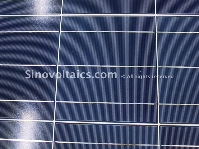
Old-fashioned polycrystalline silicon PV module with 3BB cells
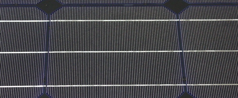
Polycrystalline silicon PV module with 5BB cells
Even though the higher quantity of busbars increases the shading of the solar cell, yet the overall performance of multi-busbar cells is much better than that of conventional 2BB or 3BB cells. Why is that so?
Key aspects are the reduction of the effective finger length between the busbars, which reduces finger resistance losses, as well as the lesser impacts of micro cracks.
As micro cracks typically occur between busbars, the impact of such cracks is thus reduced towards smaller affected cell slices between two busbars. Thus, as compared to conventional 2BB and 3BB cells, the long-term reliability of a multi-busbar cell even in the event of micro cracks is higher.
Also, on the cost side, the multi-busbar design with thinner busbars allows for an overall reduction of the expensive silver paste.
Particularly outstanding is in this regard LG’s CELLO wire technology – CELLO stands for the lengthy name Cell connection with Electrically Low loss, Low stress, and Optical absorption enhancement.
Instead of the standard 3 busbar design, the company uses 12 round, thin circular-shaped wires which cover the entire surface of the solar cells. LG’s prime CELLO technology product is its NeON 2 PV module.
Busbar-less cells
Contrary to the multi-busbar approach, other companies are going an entire busbar-less way, spearheaded by California-based Solaria.
Solaria’s proprietary zero busbars and zero-wire design use overlapping solar cell segments that are directly electrically connected with each other.
The advantages of busbar-less cells are obvious:
- much better power production-to-space ratio
- more flexible module size design – conventional module design is limited by cell size and spacing requirements
- significantly reduced shading
- less potential cell-inherent defects such as micro cracks, often caused by cell soldering
- saving on busbar material costs
In the framework of its technology, Solaria also developed equipment and techniques for slicing solar cells into segments and then stringing the cell segments together. It can be integrated with existing production lines. (1)
Busbar material – cost reduction
While the multi-busbar and busbar-less designs are focusing on increasing performance and reliability, other approaches focus on the reduction of material costs, primarily by minimizing the cost-driving silver metallization of the busbars as with the dash-line busbar designs (see below).
Another currently promoted approach is the entire replacement of silver for the solar cell metallization with alternative materials such as tin or nickel. A few years ago, German Roth & Rau – now part of Meyer Burger – introduced nickel busbars for both front and rear side metallization, while the German Fraunhofer Institute for Solar Energy Systems (ISE) has been pursuing research on copper-based metallization (2).
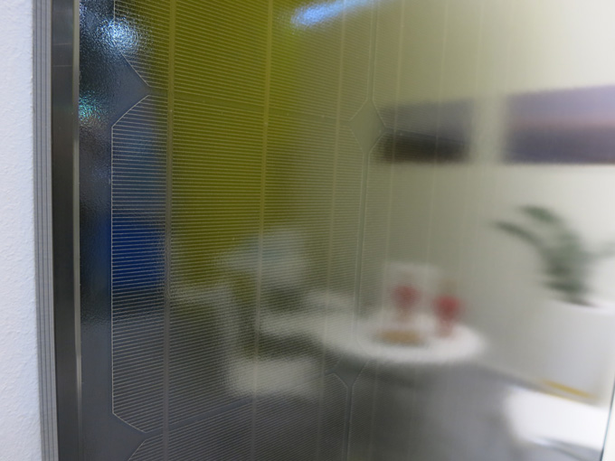
Dash-line pattern busbars
The industry has in recent years come up with a more cost-efficient alternative to the traditional full-line busbars: dash-line pattern busbars, reducing the usage of the expensive silver paste. Various types of dash-line busbars exist, such as 3-dash, 5-dash, 6-dash, and even 8-dash busbars.

Cells with dash-line pattern busbars
As cost reductions often go hand in hand with long-term quality and reliability reductions, this can also be observed for the dash-pattern busbar inventions.
Research has shown that dash-pattern busbars are more prone to potential cracking and power degradation – problems that increase with the number of dash lines, with thermal stress accumulating and cracking happening at the corners of a busbar and thus increasing with the number of dashes. (3)
Tab wire optimization: round wires and colored wires
When optimizing the performance of solar cells, the tab wires also offer room for improvement. One such improvement involves the usage of round tab wires, which – in comparison to the rectangular-shaped wires – come with less shading due to their reduced space.
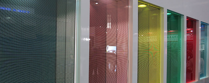
The usage of colored tab wires has primarily aesthetical reasons and researchers as well as even manufacturers have come up with solutions in this regard the improve the overall visual appearance of solar modules.
An example is the All Black solar PV modules with p-type mono cells from Perlight Solar, which use black tab wire to create a fully black module.
Perlight AllBlack solar modules at Intersolar Munich 2015
Maarten Romijn
on 12 Aug 2016Niclas
on 19 Aug 2016Wong Yiu Chung
on 13 Jun 2017warren
on 01 Apr 2019Abdelaziz
on 17 Jun 2018