
EL Testing Insights: Impact of Microcracks on Solar Power Plants
Significant scientific solar PV literature has been dedicated to the impact of microcracks by various research institutes and universities. These papers suggest that cracks in solar panels can lead to hotspots, a higher probability of PID, and in turn, high rates of degradation. These defects typically are not visible to the naked eye and require a specialized method to visualize. That being electroluminescence or typically known as EL imaging. This article explores what EL imaging is, the different types of microcrack and quality issues that can be detected, and to what extent these faults can impact asset performance over the lifetime.
Working principle of EL when testing solar panels
Solar PV modules are designed to convert sunlight into electricity. Alternatively, they can also work as LEDs. As seen in Figure 1, by applying current the solar panel can cause the semiconductor materials to emit electroluminescent radiation - or infrared light (NIR or IR). A CCD and/or GaAs camera can detect this light in a dark room and provide an image from which failures can be visualized on a solar module that impact silicon solar cell efficiency.
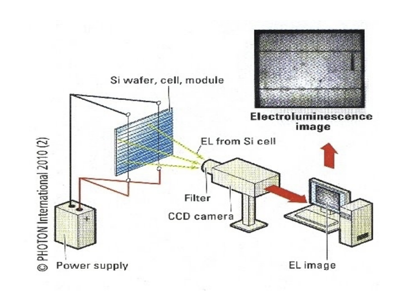 Figure 1. Working Principle of EL Imaging by Photon International
Electroluminescence imaging during an EL inspection allows an operator or product owner the ability to see faults that are detectable with the visible eye. The light output increases with the local voltage so that regions with poor contact show up as dark.
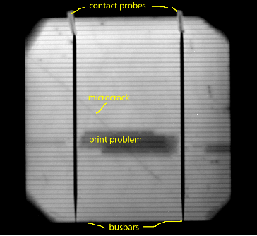 Figure 2. Education visualization of an EL image and detecting quality issues
As seen in Figure 2, the intensity of the light given off is proportional to the voltage, so poorly contacted and inactive regions show up as dark areas. The microcrack and printing problem are not detectable with visual inspection.
EL testing in a solar PV panel production line
All modules are EL tested by manufacturers before lamination and at the end of the production line, alongside IV and Hi-pot tests. An EL image can show many types of cell-inherent defects, not only microcracks. The pass or fail criteria of the EL image depends on the type of crack and the quantity per cell or module.
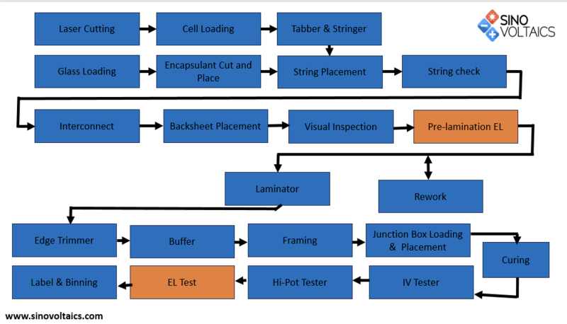 Figure 3. Layout of a solar panel supplier production line
Solar panels that fail EL imaging before lamination are usually taken out for re-work. The root causes here can be various but can include issues with incoming control, handling, stringer, and/or layout problems. Catching these faults before lamination is critical to reduce solar PV waste as most issues can be addressed by replacing cells, optimizing procedures, and training personnel. After lamination, modules are again tested with an EL tester. This usually goes hand in hand with IV, Hi-Pot, and visual inspection. This is to detect faults during lamination, edge trimming, or junction box soldering.
All in all, before or after lamination the operator or automatic software program detects and classifies modules according to the type and amount of cracks or production faults that are found.
Figure 4 visualizes some of the faults that can be seen during manufacturing or even before, during, or after project installation. Depending on the amount and type of cracks and/or faults the modules are classified A (pass), B or C (fail). An example here is that there may be x allowed number of cross cracks in an A module, but one sole branched/dendritic crack is immediately a Class C fail module. Much like IV data and graphs, developers and project owners may request the receipt of high-definition (HD) EL images of the solar panels they received.
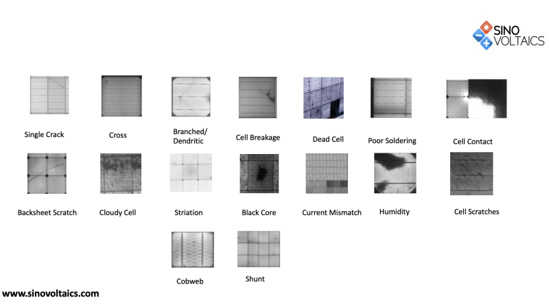 Figure 4. Some, but not all example Images of Faults Detectable via EL Testing
Sinovoltaics has an in-house EL standard for full cell, half-cut, and shingled modules that can be used by procurement officers in their discussions with suppliers on the pass, critical, or major pass/fail criteria. Moreover, during factory audits or production monitoring, Sinovoltaics makes use of its proprietary SELMA (Sinovoltaics EL Mass Analysis) (SELMA) software. SELMA is AI software that is accepted by all the major module manufacturers, works along the supplier’s cycle times, and has 10 years of data to detect more than 15 types of defects.
Having the EL images allows the site owner to have a baseline from which to work. Particularly, given that microcracks may also occur during the handling, installation, and operation of the solar asset. A highly recommended best practice is then also to conduct EL imaging in-situ at the PV power plants as a good measure.
Solar power plant EL Testing
As noted earlier, microcracks can still occur during the transportation, installation, and operation of your PV assets. Cracks occur from transportation due to large shocks, not following installation manual guidelines, and poor storage practices. Installation induced cracks can range from leaning or walking on a module, dropping tools, or bumping against the backside of a solar panel. Lastly, operational root causes are thermodynamic stresses from the substructure and climate (wind or snow loads) or severe weather events like hail or other. Therefore, implementing best practices during each phase can mitigate these errors from occurring.
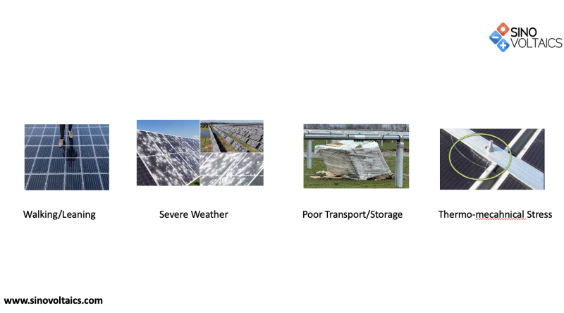 Figure 5. Potential Root Causes of non-manufacturing cracks
In order to determine that non-production faults have taken place and if evidence suggests from the supplier HD EL images that no faults were seen; EL imaging can be done at the project site. Though typically this is a result of detection by the EPC or O&M company of poor string performance, which then would lead to IR drone imaging. Following this, if the thermal images indicate hot spots or other faults, EL imaging is done of that string or part of the park. This is the weather allows and the test method as seen in Figure 6 is opted for by the asset owner. Alternatively, some opt for UV photoluminescence testing. Nonetheless, IEC62446 currently recommends IR imaging at near FAC, though as discussed in the earlier Sinovoltaics EL webinar, EL imaging will be included as a best practice. It is important that alongside the images a strong software to recognize the different faults is used to evaluate the type and severity of the different issues seen.
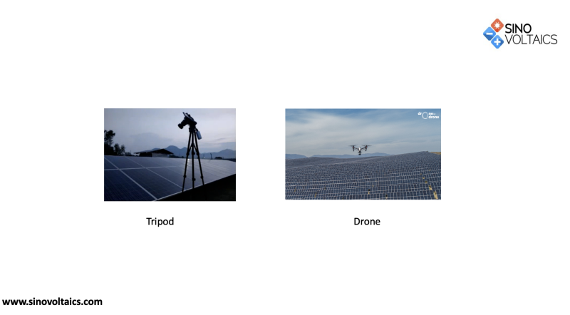 Figure 6. EL project site methods (Drone and Tripod)
Alongside detecting interconnect failure and cracks other faults can be detected as seen in Figure 7. LID and LETID could be more likely in PERC modules, though PID is often a challenge regardless of cell technology. Moreover, PID images will get worse as they reach the end of the string nearing the negative end. Scratches delamination can often be seen visually, but the either drone or tripod will show these failure modes clearly.
Do note that even small cracks or faults with Class A modules, or worse yet Class B can grow or propagate due to the cyclic weather events of the project location. Below we explore the impact thereof.
Microcracks propagation and how it plays role in hot-spots, accelerated degradation rates, and PID
Current scientific literature by NREL and Boise State University indicates that microcracks or faulty interconnections (also detectable in EL images) have an impact on the overall degradation rate of a PV module. Potentially accelerating the rate by 15%.
Modules and cell architectures are getting thinner and bigger, which alongside the many benefits also brings operational risks from a thermomechanical standpoint and propagation of microcracks. These occur either due to the higher frequency of heat waves due to the climate crisis, or heavier wind loads which can make cracks grow. With this the likelihood of hot spots or increases in temperature on cracked cells which in turn accelerates the degradation of the module. Thus, becoming a non-linear trend instead of the guaranteed linear warranty provided by the manufacturer.
As such, the mitigation of cracks either from manufacturing, transport, installation, or operation is critical to meet and exceed calculated financial returns. Sinovoltaics strives to provide with its services zero risk projects.
All stated papers can be found in the following link.
Conclusion
EL imaging is the best way to detect microcracks, interconnect faults, or defects rooting either from manufacturing, transport, installation, or operation. Mitigating these cracks is essential to stay in line with the linear degradation expectations and in turn, operational excellence. Having underlined the origin and effect of microcracks; Sinovoltaics as an independent quality acceptance and control auditor is your partner in managing these risks and maximizing solar plant ROI.
Our team can either provide documentation to aid in contract negotiations with regard to quality or execute factory audits and/or production monitoring to reduce the risk of cracks from a production. Moreover, with partners Sinovoltaics can assist in doing site EL imaging during different phases of the construction or operation to detect site failure modes, be it from manufacturing, installation, or operation.
