IEC 61215 MQT 11: Thermal Cycling Test for Solar Modules — Everything You Need to Know
Solar panels are exposed to drastic temperature swings throughout their operational lifetime, from freezing winter nights to scorching summer afternoons. The IEC 61215 MQT 11 thermal cycling test is specifically designed to assess whether a photovoltaic module can withstand these repeated thermal stresses without degradation. Here's a complete breakdown of what this test involves and why it matters for module qualification.
What is the MQT 11 Thermal Cycling Test?
MQT 11, defined in IEC 61215-2:2021, is one of the core qualification tests in the IEC 61215 test sequence for terrestrial photovoltaic modules. Its purpose is straightforward:
To determine the ability of the module to withstand thermal mismatch, fatigue and other stresses caused by repeated changes of temperature.
In other words, MQT 11 simulates accelerated aging by repeatedly cycling the module between extreme hot and cold temperatures while monitoring electrical continuity. If a module's solder joints, cell interconnects, encapsulant adhesion, or junction box integrity are vulnerable, this test will expose those weaknesses.
Required Apparatus
To run MQT 11, laboratories need the following equipment:
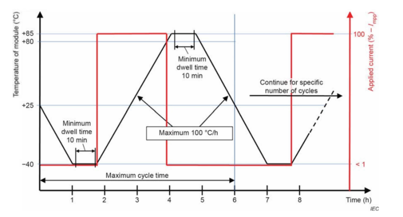
• A climatic chamber with automatic temperature control, air circulation means, and condensation-minimization capability, capable of cycling modules through the full temperature profile shown in Figure 1.
Figure 1
• Mounting means that allow free circulation of surrounding air around the module(s), so that modules are thermally isolated from the support structure (the thermal conduction of the mount must be low).
• Measurement instrumentation with accuracy of ±2.0 °C and repeatability of ±0.5 °C for recording module temperature throughout the test.
• A continuous current supply set to the technology-specific current value.
• Current flow monitoring equipment to track continuity through each module during the test.
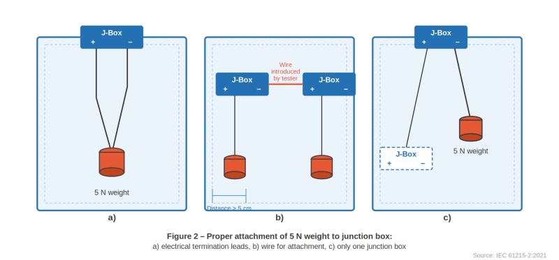
• A 5 N weight capable of being attached to the electrical termination leads of the module, to stress-test the junction box attachment.
Test Procedure
1. Attach temperature sensors and install the module
Attach a suitable temperature sensor to the front or back surface of the module near the middle. If multiple modules of the same type are tested simultaneously, monitoring just one of them for temperature suffices.
Install the module(s) at room temperature inside the chamber. At this point, attach a single 5 N weight to the junction box. As shown in Figure 2, the weight may be applied in one of two ways:
• Using the electrical termination leads so the weight hangs vertically from the junction box (Figure 2a); or
• Via a wire introduced by the tester, positioned at least 5 cm above the floor or module frame (Figure 2b).

For flexible modules, mount according to the manufacturer's documentation, using prescribed substrate, adhesive, and attachment/mounting means.
2. Connect the current supply
Connect the positive terminal of the module to the positive terminal of the power supply. During the heat-up cycle (from −40 °C to +80 °C), set the continuous current flow to the technology-specific value.
During cool-down, at the −40 °C dwell phase and at temperatures above 80 °C, reduce the continuous current to no more than 1.0% of the measured STC peak power current, this allows continuity monitoring without generating significant heat.
If the temperature rises too fast (greater than 100 °C/h) at the lowest temperature, the start of the current flow can be delayed until the module temperature has reached −20 °C.
3. Run the thermal cycles
Close the chamber and subject the module(s) to repeated cycling between (−40 ± 2) °C and (+85 ± 2) °C in accordance with the temperature and current profile shown in Figure 1.
Key parameters:
• Rate of change: must not exceed 100 °C/h
• Minimum dwell time: at least 10 minutes at each temperature extreme
• Maximum cycle time: must not exceed 6 hours (unless the module has particularly high heat capacity requiring a longer cycle)
• Number of cycles: as specified in the relevant test sequence
Air circulation around the modules must ensure each unit under test meets the required temperature cycling profile.
4. Record and monitor
Throughout the test:
• Record the module temperature continuously.
• Monitor current flow through each module.
• Document in the test report the actual dwell duration at both the high and low temperature extremes.
Note: In a module with parallel circuits, an open circuit in one branch will cause a discontinuity in the voltage, but not cause the current to go to zero.
Final Measurements
After completing all cycles, allow the module a minimum recovery time of 1 hour at (23 ± 5) °C and relative humidity below 75%, under open-circuit conditions. Then repeat the following measurements:
• MQT 01 — Visual inspection
• MQT 15 — Wet leakage current test
Pass/Fail Criteria
A module passes MQT 11 if it meets all three of the following requirements:
1. No interruption of current flow during the test. In a module with parallel circuits, a discontinuity in current flow indicates an interruption of flow in one of the parallel circuits — this constitutes a failure.
2. No evidence of major visual defects, as defined in IEC 61215-1:2021.
3. Wet leakage current must meet the same requirements as for the initial measurements.
Why MQT 11 Matters for PV Module Certification
Thermal cycling is one of the most revealing stress tests in the IEC 61215 qualification sequence. Temperature changes cause differential expansion and contraction between dissimilar materials — cells, encapsulant, glass, backsheet, and metal interconnects. Over time, this creates fatigue at solder joints and cell interconnects, potential delamination, and junction box failures.
A module that passes MQT 11 demonstrates that its design and manufacturing quality can withstand the thermal fatigue encountered over a typical 25–30 year field lifetime. Combined with other tests in the IEC 61215 sequence (such as damp heat, humidity freeze, and mechanical load tests), MQT 11 forms a critical part of the comprehensive qualification framework that buyers, project developers, and insurers rely on.
Need to Find an Accredited Lab for IEC 61215 Testing?
Sinovoltaics Lab Advisor helps you identify and compare accredited test laboratories for PV module qualification testing, including MQT 11 thermal cycling and the full IEC 61215 sequence. Get connected with the right lab for your project quickly and transparently.
Find your IEC 61215 test lab → labadvisor.sinovoltaics.com
Source: IEC 61215-2:2021 — Terrestrial photovoltaic (PV) modules – Design qualification and type approval – Part 2: Test procedures, Section 4.11