IEC 61215 MQT 12: Humidity-Freeze Test for Solar Modules
Moisture infiltration followed by freezing temperatures is one of the most damaging combinations a solar panel can face in the field. The IEC 61215 MQT 12 humidity-freeze test is designed to assess whether a photovoltaic module can withstand exactly this scenario — high humidity at elevated temperature, immediately followed by sub-zero conditions. Here is a complete breakdown of what the test involves and why it matters.
What is the MQT 12 Humidity-Freeze Test?
MQT 12, defined in IEC 61215-2:2021, is a core qualification test in the IEC 61215 test sequence for terrestrial photovoltaic modules. Its purpose is:
To determine the ability of the module to withstand the effects of high temperature and humidity followed by sub-zero temperatures.
Importantly, this is not a thermal shock test. The transition between the hot-humid phase and the cold phase follows a controlled rate of change, distinguishing MQT 12 from tests that apply sudden, extreme temperature differentials. The test targets a different failure mode: moisture absorbed during the humid phase that then expands and causes mechanical damage as it freezes.
Required Apparatus
To run MQT 12, laboratories need the following equipment:
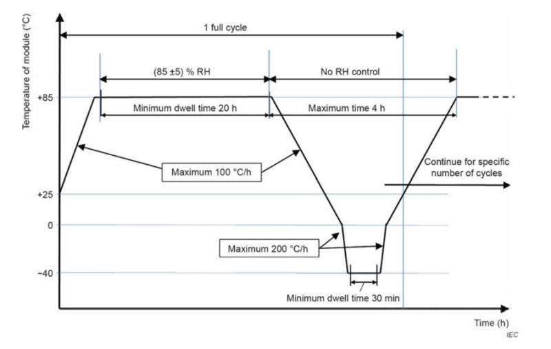
• A climatic chamber with automatic temperature and humidity control, capable of subjecting one or more modules to the humidity-freeze cycle shown in Figure 1.
• Mounting means that allow free circulation of surrounding air around the module(s), so that modules are thermally isolated from the support structure (the thermal conduction of the mount must be low).
• Measurement instrumentation with accuracy of ±2.0 °C and repeatability of ±0.5 °C for measuring and recording the temperature of the module(s).
• Means for monitoring the continuity of the internal circuit of each module throughout the test.
Test Procedure
1. Attach temperature sensors and install the module
Attach a suitable temperature sensor to the front or back surface of the module(s) near the middle. If more than one module of the same type is tested simultaneously, it will suffice to monitor the temperature of one of the test modules.
Install the module(s) at room temperature in the climatic chamber. For flexible modules, mount according to the manufacturer's documentation with prescribed substrate and adhesive or attachment/mounting means during the test.
2. Connect the current supply
Connect each module to the appropriate current supply by connecting the positive terminal of the module to the positive terminal of the power supply and the second terminal accordingly.
During the humidity-freeze test, set the continuous current flow to no more than 0.5% of the measured STC peak power current. If 0.5% of the measured STC current is less than 100 mA, then 100 mA may be applied instead.
3. Run the humidity-freeze cycles
Close the chamber and subject the module(s) to 10 cycles in accordance with the profile shown in Figure 1.
Key parameters:
• Maximum temperature: +85 °C
• Minimum temperature: −40 °C
• Relative humidity: maintained at (85 ± 5) % RH during the high-temperature dwell phase; no RH control during the cold phase
• Humidity tolerance: within ±5% of the specified value when the temperature is at the maximum value of 85 °C
• Temperature tolerance: maximum and minimum temperatures within ±2 °C of the specified levels
• Ramp up (to +85 °C): maximum 100 °C/h
• Ramp down (to −40 °C): maximum 200 °C/h
• Ramp back up (to +85 °C): maximum 200 °C/h
• Minimum dwell time at +85 °C: 20 hours
• Minimum dwell time at −40 °C: 30 minutes
• Maximum time for the cold phase: 4 hours
Air circulation around the module(s) must ensure compliance with each module under test meeting the temperature cycling profile.
4. Record and monitor
Throughout the test, record the module temperature and monitor the current and voltage through the module.
Temperature and Humidity Profile
The diagram below shows the full cycle profile for MQT 12. The blue line traces the module temperature. The blue shaded zone at the top of the chart marks the phase where (85 ± 5) % relative humidity is actively controlled. Once the temperature drops below the high-temperature dwell, humidity control is no longer applied.

Final Measurements
After completing all 10 cycles, allow the module a recovery time between 2 and 4 hours at (23 ± 5) °C and relative humidity less than 75%, under open-circuit conditions. Then repeat the following measurements:
• MQT 01 — Visual inspection
• MQT 15 — Wet leakage current test
Pass/Fail Criteria
A module passes MQT 12 if it meets all three of the following requirements:
1. No interruption of current flow or discontinuity in voltage during the test. In the case of a module with parallel circuits, a discontinuity in current flow indicates an interruption of flow in one of the parallel circuits — this constitutes a failure.
2. No evidence of major visual defects, as defined in IEC 61215-1:2021.
3. Wet leakage current must meet the same requirements as for the initial measurements.
Why MQT 12 Matters for PV Module Certification
The humidity-freeze test replicates one of the harshest real-world conditions a solar module encounters in climates with cold winters — high summer humidity followed by freezing. Moisture that penetrates the encapsulant, laminate edges, or junction box during the humid phase can expand when it freezes, causing delamination, cell cracking, corrosion of metallization, and loss of electrical continuity.
A module that passes MQT 12 demonstrates that its sealing, lamination quality, and materials are resilient to this freeze-thaw moisture cycle. Together with MQT 11 (thermal cycling) and MQT 13 (damp heat), MQT 12 forms part of the environmental stress sequence in IEC 61215 that gives buyers and project developers confidence in long-term field reliability.
Need to Find an Accredited Lab for IEC 61215 Testing?
Sinovoltaics Lab Advisor helps you identify and compare accredited test laboratories for PV module qualification testing, including MQT 12 humidity-freeze and the full IEC 61215 sequence. Get connected with the right lab for your project quickly and transparently.
Find your IEC 61215 test lab → labadvisor.sinovoltaics.com
Source: IEC 61215-2:2021 — Terrestrial photovoltaic (PV) modules – Design qualification and type approval – Part 2: Test procedures, Section 4.12