What Is IEC 61215 MQT 17? Solar Panel Hail Test Standard Explained

20 juli 2026

Hailstorms are a significant and growing concern for solar installations worldwide. A single severe hail event can cause widespread cracking, delamination, and electrical failure across an entire solar field. The IEC 61215 MQT 17 hail test is designed to verify that a photovoltaic module can withstand the mechanical impact of hailstones without sustaining damage that compromises its performance or safety. Here is a complete breakdown of what the test involves.

What is the MQT 17 Hail Test?
MQT 17, defined in IEC 61215-2:2021, simulates the impact of hailstones on a solar module using spherical ice balls launched at controlled velocities. Its purpose is:
To verify that the module is capable of withstanding the impact of hail.

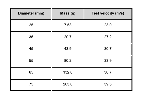
The standard minimum test uses 25 mm diameter ice balls launched at 23.0 m/s. For hail-prone locations, larger ice balls may be required. The test report must indicate what ice ball diameter and test velocity were used.

Ice Ball Specifications — Table 1
The standard defines the following ice ball masses and test velocities for different hailstone diameters:

Required Apparatus
The following equipment is required to carry out MQT 17:
Moulds of suitable material for casting spherical ice balls of the required diameter. Minimum requirement is a diameter of 25 mm.
A freezer controlled at (−10 ± 5) °C.
A storage container for storing the ice balls at a temperature of (−4 ± 2) °C.
A launcher capable of propelling an ice ball at the specified velocity within ±5%, so as to hit the module within the specified impact location. The path of the ice ball may be horizontal, vertical, or at any intermediate angle, as long as the test requirements are met.
A rigid mount for supporting the test module by the method prescribed by the manufacturer, with the impact surface normal to the path of the projected ice ball.
A balance for determining the mass of an ice ball to an accuracy of ±2%.
A velocity measuring instrument to an accuracy of ±2%. The velocity sensor shall be no more than 1 m from the surface of the test module.

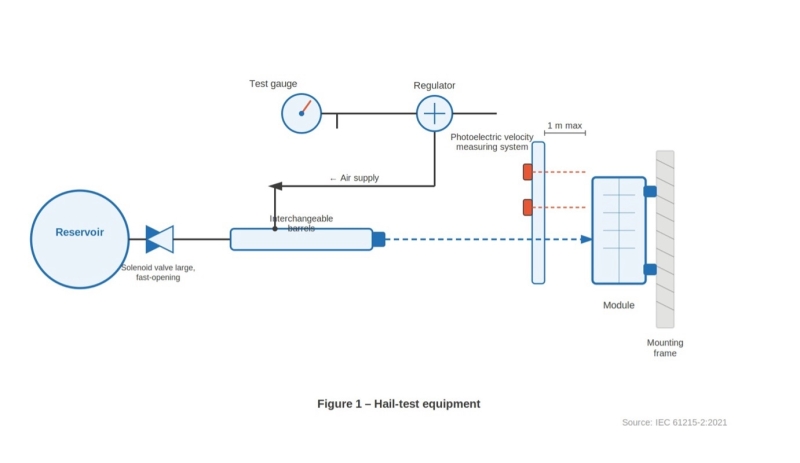
An example of suitable apparatus is a horizontal pneumatic launcher, a vertical module mount, and a photoelectric velocity meter — as shown in Figure 1. Other types including slingshots and spring-driven testers have also been successfully utilized.


Test Procedure
Step 1 — Prepare the ice balls
Using the moulds and the freezer, make a sufficient number of ice balls of the required size for the test, including some for the preliminary adjustment of the launcher. Examine each one for cracks, size, and mass. An acceptable ball must meet all of the following criteria:
• No cracks visible to the unaided eye
• Diameter within ±5% of that required
• Mass within ±5% of the appropriate nominal value in Table 1

Step 2 — Store the ice balls
Place the balls in the storage container and leave them there for at least 1 hour before use.

Step 3 — Prepare the launcher
Ensure that all surfaces of the launcher likely to be in contact with the ice balls are near room temperature. Fire trial shots at a simulated target and adjust the launcher until the velocity of the ice ball, as measured with the velocity sensor in the prescribed position, is within ±5% of the appropriate hailstone test velocity.

Step 4 — Mount the module
Mount the module according to manufacturer specifications. The module shall be at room temperature, with the impact surface normal to the path of the ice ball. For flexible modules, mount per the manufacturer's documentation with prescribed substrate and adhesive or attachment/mounting means. If the manufacturer's specified application allows both rigid and flexible mounting, test on the worst-case condition and document the test configuration in the test report.

Step 5 — Fire and inspect
Take an ice ball from the storage container, place it in the launcher, aim at the first impact location, and fire. The time between removing the ice ball from the container and impact on the module shall not exceed 60 seconds.


After each shot, inspect the module at the impact area for any visual signs of damage. Errors of up to 10 mm from the specified location are acceptable.

Step 6 — Complete all impact locations
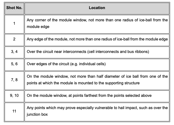
If the module is undamaged, repeat for all other impact locations as defined in Table 2 and illustrated in Figure 1.

Impact Locations — Table 2


Final Measurements
After completing all 11 shots, repeat the following measurements:
MQT 01 — Visual inspection
MQT 15 — Wet leakage current test

Pass/Fail Criteria
A module passes MQT 17 if it meets both of the following requirements:
1. No evidence of major visual defects, as defined in IEC 61215-1:2021.
2. Wet leakage current must meet the same requirements as for the initial measurements.

Why MQT 17 Matters for PV Module Certification
Hail damage is one of the most visible and commercially significant failure modes in solar, high-profile hailstorm events have resulted in hundreds of millions of dollars in insurance claims and project write-downs. Module glass cracking, cell fracture, and delamination caused by hail impact can lead to immediate power loss, accelerated degradation through moisture ingress, and safety risks from exposed live components.

For project developers, insurers, and lenders, MQT 17 certification provides a baseline assurance that a module's frontsheet and structural integrity meet a minimum standard of impact resistance. For projects in hail-prone regions — parts of the US, Europe, Australia, and China — specifying modules tested at larger ice ball diameters (45 mm or above) provides additional confidence beyond the standard 25 mm minimum.

Need to Find an Accredited Lab for IEC 61215 Testing?
Sinovoltaics Lab Advisor helps you identify and compare accredited test laboratories for PV module qualification testing, including MQT 17 hail testing and the full IEC 61215 sequence. Get connected with the right lab for your project quickly and transparently.
Find your IEC 61215 test lab → labadvisor.sinovoltaics.com

Source: IEC 61215-2:2021 — Terrestrial photovoltaic (PV) modules – Design qualification and type approval – Part 2: Test procedures, Section 4.17

Place comment