

In this series about the solar balance of systems, we will introduce and discuss various components, their specific technology features, and roles in a solar PV system, starting in this part 1 with solar cables and wires.
Indeed, building a quality, safe and profitable solar PV plant with a good return on investment (RoI) is the most important objective of investors, project owners, and also developers.
The quality, safety, and profitability of a solar plant do not only depend on the workmanship and efficiency of PV modules and the reliability of the inverter, but also on the balance of system components that for many seem not to have direct or not much impact.
However, the role of the balance of system ‘army’ in the common battle for the commercial and operational success of a PV system cannot be too underestimated. A proper selection of balance of system components is crucial in the long term. Low-quality components may at least result in higher maintenance costs if not even replacements of modules and inverters.
Wiring is often not considered to be a critical factor, however, neglecting correct wiring and using material that is not suitable for solar applications can compromise the overall lifetime of a system.
Definition of the balance of the system
The term balance of system, often just simply abbreviated as BOS, includes many components that are part of a solar power system. Commonly, these are:
- Cables and Wires
- Charge Controllers
- Combiner Boxes
- Connectors
- Disconnects & Fuse Boxes
- Mounting Systems
- Recombiners
Depending on the configuration there may also be solar trackers, solar energy concentrators, energy meters and monitors.
Better than enumerating all that is included in the balance of the system, BOS can also simply be summed up as ‘anything which is (somehow) part of a PV solar power system, and is not a solar module, inverter or a battery, is part of the balance of the system’.
The definition of BOS will tend to become unclear as technology developments yield products that could be integrated right into the module itself.
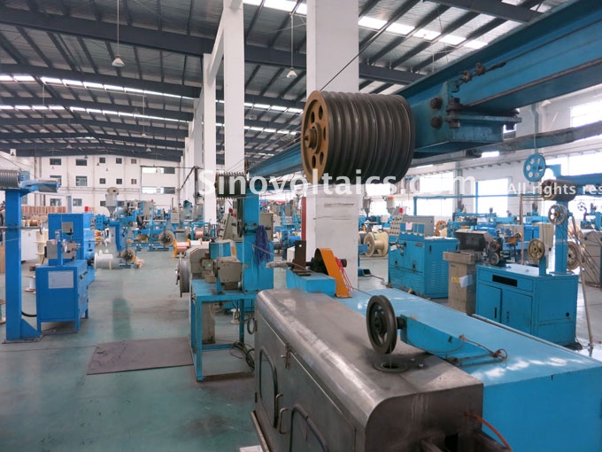
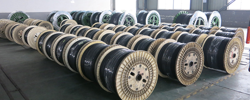
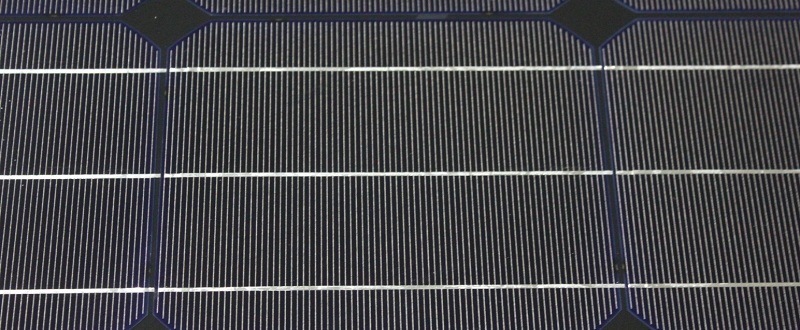
Solar cables in the making
What are cables, and what are wires?
Cables and wires are considered as veins and arteries of any electrical power system.
In most cases, electricity is generated at one device and consumed at another. This transfer of electrical signals is facilitated by employing a proper network of cables, wires, and buses.
Solar energy systems are no different. Electrical energy may be generated by a solar module, mounted on the roof, and may be required to power loads in the basement. This transportation of electricity is made possible by using solar cables and wires.
While cables and wires are generally used to represent the term ‘wiring’, there is a major difference between the two.
Wires
A wire is a conductive material (conductor) that is usually made of (tinned) copper or aluminum, both of which have very good conductivity, ductility, and malleability. Basically, there are two forms of wires:
- single strand, or simply: solid wire or single wire
- group of strands, or simply: stranded wire
Stranded wires are made of multiple conductive material strands that are wounded together to form one single wire core. These strands are very small in diameter. On the other hand, single-strand wires literally consist of one single strand of conductive material which is larger in diameter as compared to a single strand of a stranded wire.
There are significant physical and application differences between these two types: while stranded wires are generally used in applications in which they are subject to frequent movement or even vibrations, solid core wires are suitable for fixed non-moving applications, such as in domestic applications such as electric wiring being plastered in walls.
The reason for this is that copper, the most commonly used conductor, is sensitive to mechanical stress such as vibrations that can potentially make it increasingly fragile until it finally cracks at some point.
As a result, in applications where the cables and wires are exposed to mechanical stress, stranded wires due to their small diameter and being wounded together, provide for much better flexibility.
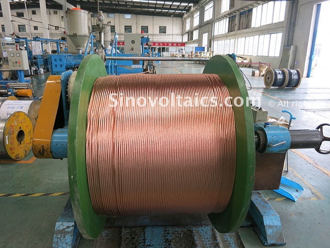
The large drum of copper wire
Cables
A cable is a group of two or more conductors that are twisted or bonded together, surrounded by an insulating layer that itself is within a cable jacket, also called cable sheath. A cable may contain any number (more than one) of conductors and varies in its external diameter depending on the number of conductors.
In DC circuits, cables commonly consist of at least a current-carrying live wire within an insulation layer that is usually colored red, and a negative wire usually surrounded by a black-colored insulation layer.
In other applications such as AC systems, cables consist of a live wire that carries the current, a neutral wire that completes the electric circuit, carrying current away from the device, and also feature a third ground wire. This ground wire or earth wire is a safety wire that connects the casing of the device to the ground and thus preventing fault from making the casing of a device live (current-carrying). Usually, the earth wire is colored green or yellow (or dual green-yellow).
It is important to remember that cable coloring differs significantly per country and application type! For example in the USA, in 120V single-phase AC applications, the insulation layers of live wires are colored black, and those of neutral wires are colored white or grey. Below is a non-exhaustive table of power cable insulation color codes of some countries.
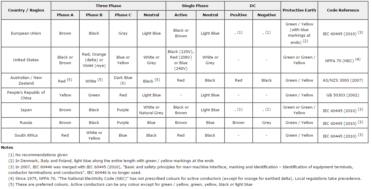
Table of power cable insulation color codes per country (source: OpenElectrical.org)
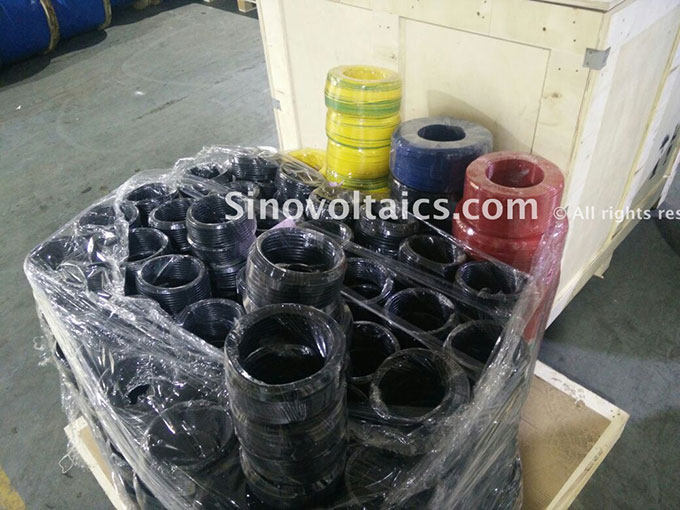
Different solar sheath colors differ per jurisdiction
Electrical cables can be categorized into different sub-types, such as telephone cables, computer cables, television cables, home cables and video cables. These sub-types also work on different interface technologies, for example, video cables can be subdivided into HDMI (High-Definition Multimedia Interface) cables and DVI (Digital Visual Interface) cables.
From a cable construction point of view, usually following four types of cables can be distinguished:
- Coaxial Cables: also called coax cables, comprise a tube of multiple (braided or meshed) conductor strands that serve as ground and surround an insulated central conductor and are used for telephone and television signal transmission. Owing to their construction, coaxial cables are very resistant to external interference and mechanical stress
- Optical Fiber Cables: consist of small optical fibers that can carry light and are commonly used for data transmission and communications
- Multicore Cables: is a type of electrical cable that is made of multiple wire cores insulated from each other and are commonly used in audio and video recording
- Twisted Pair Cables: consist of twisted pairs of conductors and are used in applications where symmetrical signal transmission is important. Twisted pair cables are less sensitive to common-mode interference due to a high common-mode rejection ratio (CMRR)
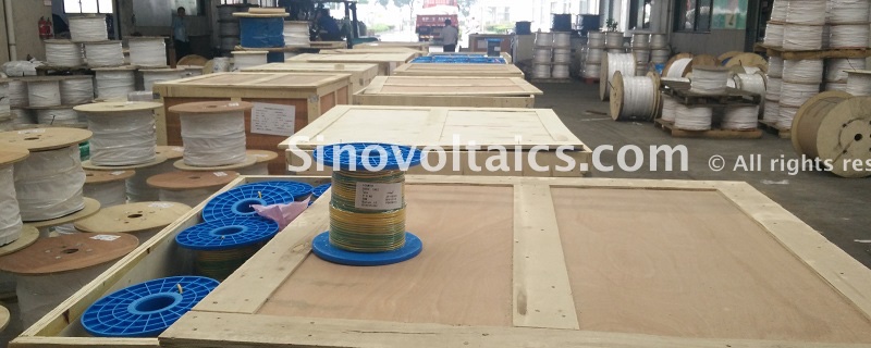
100m drum of earth cable in a factory warehouse
Solar cables and wires: types and important properties
In the solar industry, commonly three main types of DC cables and wires are used in PV installations which are:
- Earth wires
- Single core
- Twin Core
While DC cables are used for the connection between the PV components, AC cables are employed when connecting an inverter to the grid. Systems with single-phase inverters require the use of three-core AC cables and systems with three-phase inverters require the use of five-core AC cables.
There are various types of insulation and sheath materials used for the conductors of solar cables and wires, commonly used are cross-linked polyolefin (XLPO) and cross-linked polyethylene (XLPE) for solar cables and wires, and polyvinyl chloride (PVC) for the earth wires.
Commonly, solar cable and wire properties are determined by their cable-specific insulation and sheathing materials. When exposed to irradiation, the molecular structure of cable material can change.
To qualify for use in PV power applications, the insulation and sheath material of solar cables and wires must meet several crucial requirements, including:
- good weather- and UV resistance, as solar cables, lay usually outdoors and are subject to direct sun radiation and air humidity
- withstand high and low temperatures and thus be used within a temperature range of usually between -40°C to 90°C
- withstand mechanical stress from pressure, bending, or stretching as experienced during installation
- be resistant to abrasion, therefore most sheaths are made of plastics cross-linked using an electron beam
- withstand chemical stress in form of acids, alkaline solutions, and saltwater
In a typical grid-tie solar power system, wiring is needed to connect these four components together:
- the solar modules connected in a string
- the inverter connected to the module string(s)
And for off-grid systems, wiring is needed to connect:
- the charge controller
- the batteries
In a more narrow sense, solar cables and wires can also be found being incorporated in other PV components, such as solar isolators with built-in wires and MC4 connectors.
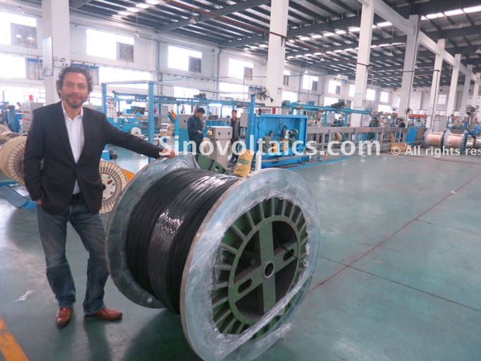
Dricus standing next to a drum of finished PV1-F solar cables in a factory
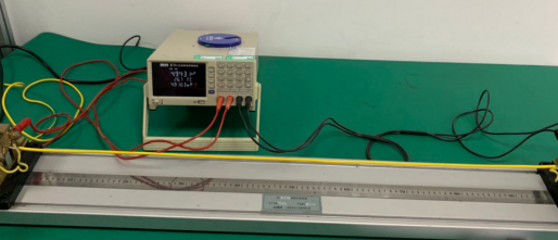
Correctly sizing the solar cables and wires in a solar system
Cables and wires have a maximum voltage and maximum current rating that indicate the maximum voltage (Volts) and current (Amps) that pass through the cable. These maximum ratings must not be exceeded.
It is very important to use the correct cable size when connecting various components of a solar energy system, this is even more true when talking about low voltage systems.
The size of the wire to be used depends upon:
- generating capacity of the solar module – the larger the current generated, the bigger the size
- distance of the solar module to the loads – the greater the distance, the bigger the size
Properly sizing the cables ensures that there is practically no overheating and very little loss of energy. On the one hand, using an undersized cable not only poses a potential for causing fire due to overheating but is also a code violation in most jurisdictions.
On the other hand, with an oversized cable, money is wasted on extra and costly conductive material which is however not needed. Usually, the higher the current rating is, the thicker and thus more expensive is the cable.
Overall, sizing wires to exactly match the ratings and thus saving some money is usually not advisable. It is safer to allow for a bit of over-sizing margin, not only to counter potential voltage drops due to overheating but also to keep options open in case more appliances should be added to the system at a later point.
It is important that the cables are not bent within their maximum permissible bend radius which is usually stipulated in the cable datasheets. In PV system cable connections, a good practice against faults and stress risks is also to lay them into protected ducts.
When sizing the cables and wires in a solar system, the overall usage environment, technologies, and type of components influence the selection of appropriate wiring. Some simple and common practices:
- module-module connections are usually enabled by connecting the positive and negative plug connector terminals of the cables of the preassembled junction boxes. For safety reasons, the positive and negative cables are laid separately. If the length of the cables is not sufficient, then special extension cables will be used. Depending on the modules’ power output, PV cables with cross-sectional areas of 2.5mm², 4.0mm², and 6.00mm² and good resistance against thermal, mechanical, and chemical stress are usually employed
- battery-inverter connections are enabled by using short and thick cables to reduce system losses and to provide for improved efficiency and reliability
- battery-charge controller connections require cables whose cross-sectional area is in accordance with the maximum output current
AWG (American Wire Gauge)
The size of the wire is often measured in AWG (American Wire Gauge) which is a standardized wire gauge measuring system.
As a rule of thumb, the bigger the AWG number, the smaller the wire. A 16 AWG wire is smaller than a 12 AWG wire, which is way smaller than a 4 AWG wire.
A large number of tools are present on the internet which help in selecting a properly sized cable.
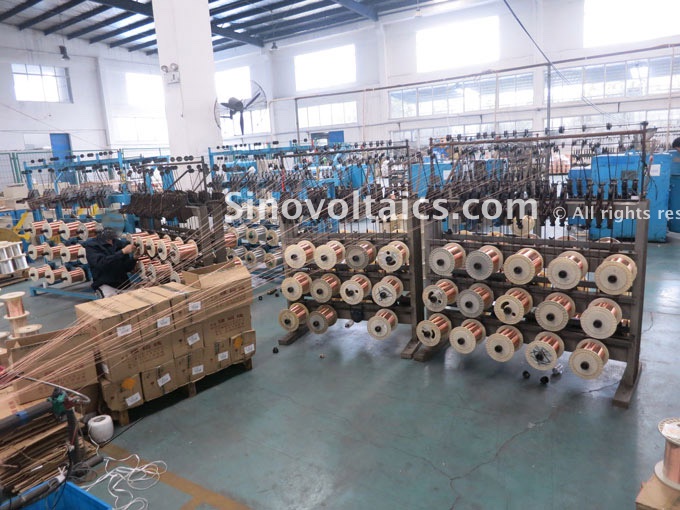
Reels of stocked copper wire being prepared for production
Applicable wire and cable standards
There are many national and international standards for (solar) cables, wires, and the specific quality requirements of the insulation and sheath of which they are made. Below is a non-exhaustive list of important standards for solar cables and wires:
- 2 PfG 1169/08.2007: often referred to as PV1-F, is an internal standard developed by TUV Rheinland, specifying the requirements for PV wire, specifying cable construction, testing, and marking requirements
- IEC/EN60228: is a fundamental standard that defines international standard wire sizes (cross-sectional areas) into different classes. IEC/EN60228 has a related German standard which is also often used: VDE0295
- UL4703: is a North-American photovoltaic wire standard developed by Underwriters Laboratories that covers single-conductor wires for interconnection wiring of the grounded and ungrounded PV systems, specifying cable construction, manufacturing, and production tests as well as marking requirements
- IEC/EN60811-403: testing insulating and sheathing materials of electric and optical cables, specifically their resistance to ozone
- IEC/EN60811-3-1: specifies requirements for high-temperature pressure resistance testing
- IEC/EN60811-2-1: specifies acid and alkaline resistance
- IEC/EN60332-1-2: involves testing of cables under fire conditions. A similar and alternative standard is VDE 0482-332-1-2:2005-06
- IEC/EN60684-2: specifies requirements regarding the non-fluorination of cables. A similar and alternative standard is VDE 0341-2:2006-08
- IEC/EN60068-2-78: specifies requirements for testing damp heat resistance
- IEC/EN50627-2-1: relates to the determination of the number of gaseous halogen acids emitted during the combustion of cable polymeric materials
- IEC/EN53516: measures the abrasion resistance of cables
- IEC/EN60216: this standard defines thermal endurance properties of electrical insulating materials
- IEC/EN60754-1: specifies testing requirements regarding gases evolved during combustion of materials from cables, specifically by testing the halogen acid gas content
- IEC/EN60754-2: specifies testing requirements regarding gases evolved during combustion of materials from cables, specifically by determination of acidity (by pH measurement) and conductivity. A similar and alternative standard is VDE 0482-754-2:2015-08
- IEC/EN61034: specifies measurements of smoke density of cables burning under defined conditions
- ISO 4892-2: this ISO standard relates to the weatherability (light, temperature, and humidity) of cable material
- SANS 1411-1: specifies materials of insulated electric cables and flexible cords
- AS/NZS5033.2012: is an Australian standard regarding the installation and safety requirements for PV arrays that mandates the usage of solar cables tested and certified according to TUV Rheinland’s standard 2 PfG 1169/08.2007
- RoHS 2002/95/EG and RoHS 2011/65/EU: relate to the restriction of the use of certain hazardous substances in electronic and electrical equipment
- ECD 2006/95/EC: This is an EC-Directive regarding the design requirements of low voltage electrical equipment
Sources and further reading:
- HardwareMarketplace: Cable Pedia – all about cables. URL: http://www.hardwaremarketplace.com/information-guide/all-about-cables.htm
- PV System Tech: Cables and connectors. URL: http://www.pv-system-tech.com/technology/cables-and-connectors/
- SolarAtlas: Using and choosing wire. URL: http://www.solaratlas.com/Related_Information_Pages/
Using%20and%20choosing_wire_for_Solar_Panel_systems.htm
badr
on 23 Sep 2018Magdy S. Abo Salem
on 08 May 2017Geof Moser
on 24 Oct 2016