


In our previous introduction article about Ohm’s Law, the importance of knowing the source resistance Rs to measure the degree of a module’s miserliness was explained. It is one of the two important variables which control how much maximum power the panel will transfer to a load.
In continuation of Ohm’s Law and miserly solar modules, in this article, we explore the core importance of heavenly impact factors on a module’s miserliness and how to measure the related performance parameters.
The importance of load resistance
Basically, from an engineering perspective, we are not so much talking about what a PV module will offer, but what it will give. It also determines how much resistance such a lucky load should represent in order to obtain maximum power from the module.
That is because of a very popular theorem in electrical engineering: the so-called maximum power transfer theorem.
This theorem basically states that in order to get the maximum power out of a source, the resistance of the load must be identical to the internal source resistance.
Incident power density – heavenly intervention
Apart from the source resistance, the second controlling parameter is the open circuit voltage (Voc). This is the terminal voltage of the module when no current is being drawn from it.
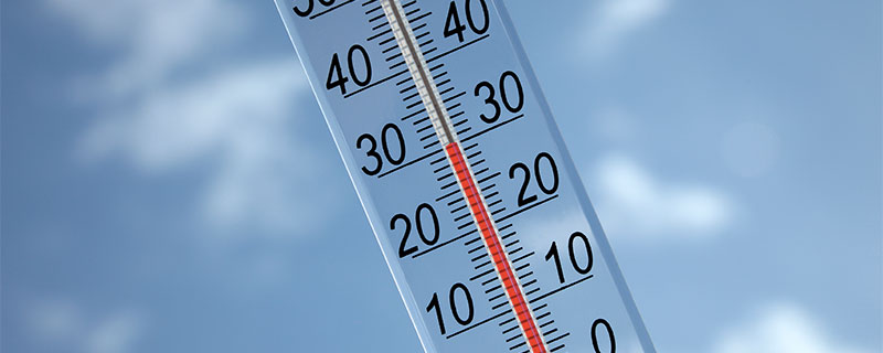
It is important to remember that these two parameters Rs and Voc are variables that depend not only on the module technology and construction but also on the ambient light level, angle, tilt, and orientation of the module with respect to the sun.
Hence, each is valid only for a specified incident power density.
Why should the module output properties like Voc and Rs depend on the incident power density? That is because the module virtually only provides an ‘arena’ for the sunlight photons to play.
Photons of the correct energy create electron-hole pairs from the silicon atoms in the panel. Electrons are minority carriers in the p-region. Some of these manage to escape recombination and breach the junction. The field in the deletion region pushes the electrons to the n-side where they are the majority carriers.
Similarly, some holes from the n-region are pushed across to the p-region. This charge accumulation creates a potential difference across the terminals.
That is why it is not the module’s raw technical specifications alone that determine its performance properties. Module properties are strongly controlled by the density of solar power incident on the module’s area.
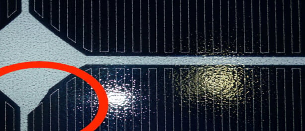
This is not the only mode of seemingly ‘heavenly intervention’. Even minor shading of a cell in the module also changes these parameters and strongly affects the performance of the cell string and as such the whole module.
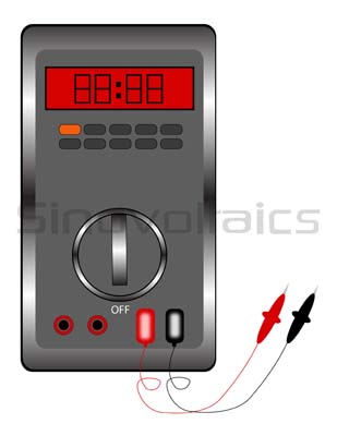
Multimeter – used to measure Amps
Measuring Voc and Rs
So how do we measure Voc and Rs, these two core parameters of solar modules (and of course other electrical systems, small and large)?
Measuring Voc is simple. All you need is a voltmeter. Unless you want to measure it under a specific set of conditions, simply position the module to face the sun and connect the voltmeter across the terminals of the module taking due note of the polarity. The voltage read on the meter is the open circuit voltage Voc of the panel under the prevalent conditions.
Of course, you know that while measuring, you should course not block the sun from the module. Theoretically, even your presence close to the ray path can affect the result due to scattering from the clothes you wear.
Evaluating Rs is trickier. Theoretically, Rs and Isc could be measured by short-circuiting the panel terminals through an ammeter (of course, with low internal resistance).
However, a short circuit condition must be avoided unless prior knowledge is available about it being a safe condition. In the case of solar modules, luckily, short-circuiting the module output will normally not damage it. But in the case of most circuits, short-circuiting the output can have tragic results.
The other alternative is to apply a variable load resistance, and note when the voltage reduces to half of the open circuit value. At this moment, the load resistance and the source resistance are sharing the total open circuit voltage equally. Hence, your load resistance is equal to the source resistance.
Needless to say, both Voc and Rs must be measured under the same lighting conditions. For this reason, formal testing on a commercial level is done in specialized labs which can produce standard illumination conditions, and have sophisticated measurement equipment.

Magzoub
on 14 Nov 2015Niclas
on 18 Nov 2015