IEC 61215 MQT 09 Hot-Spot Endurance Test: Why It Matters for Solar Module Reliability
Introduction
Hot spots remain one of the most critical reliability concerns in photovoltaic (PV) modules. They occur when one or more solar cells operate in reverse bias due to shading, cell mismatch, manufacturing defects, soiling, or damage. Under these conditions, affected cells dissipate power as heat rather than generating electricity, potentially leading to solder melting, encapsulant degradation, glass cracking, and long-term power loss.
To ensure PV modules can withstand these conditions safely, the International Electrotechnical Commission (IEC) includes the Hot-Spot Endurance Test (MQT 09) within the IEC 61215-2:2021 qualification sequence. The test evaluates whether a solar module can tolerate worst-case hot-spot conditions without experiencing significant safety or reliability issues.
This article explains the purpose, methodology, equipment requirements, pass/fail criteria, and industry significance of the IEC 61215 MQT 09 hot-spot endurance test.
What Is a Hot Spot in a Solar Module?
A hot spot develops when the operating current of a PV module exceeds the reduced short-circuit current of a shaded or defective cell.
In this situation:
• The affected cell is forced into reverse bias.
• Electrical power is dissipated as heat.
• Cell temperatures can rise significantly above neighboring cells.
• Long-term exposure may damage module materials.
According to IEC 61215-2:2021, hot spots may result from:
• Partial shading
• Soiling accumulation
• Faulty solar cells
• Cell mismatch
• Manufacturing defects
• Bypass diode malfunction
The severity of the hot spot depends on cell technology, module architecture, and electrical interconnection design.
Why Is Hot-Spot Testing Important?
While temporary shading is common in real-world PV systems, prolonged hot-spot heating can accelerate module degradation and create safety risks.
Potential consequences include:
Thermal Damage
• Solder joint melting
• Interconnect degradation
• Backsheet damage
• Encapsulant discoloration
Mechanical Damage
• Glass cracking
• Cell cracking
• Delamination
Electrical Performance Loss
• Reduced power output
• Increased leakage current
• Permanent cell degradation
Safety Concerns
• Localized overheating
• Burn marks
• Potential fire hazards in extreme cases
The MQT 09 test is designed to identify these risks before modules enter commercial deployment.
Understanding Hot-Spot Behavior
IEC 61215 identifies two primary categories of cell behavior:
Low Shunt Resistance Cells
For low shunt resistance cells:
• Worst-case conditions occur when the entire cell or a large portion of it is shaded.
• Heating tends to be highly localized.
• Hot-spot failures can develop rapidly.
These cells often exhibit significant variation in reverse-bias performance, making careful cell selection essential during testing.
High Shunt Resistance Cells
For high shunt resistance cells:
• Worst-case conditions usually occur during partial shading.
• Junction breakdown develops more slowly.
• Elevated temperatures require longer exposure periods.
Because different cell technologies respond differently, IEC 61215 includes technology-specific procedures for identifying worst-case shading conditions.
Module Configurations Covered by MQT 09
The standard recognizes several module interconnection architectures:
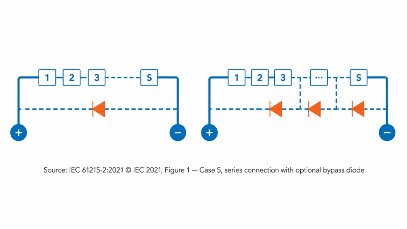
Case S: Series Connection
All cells are connected in a single series string and may be protected by one or multiple bypass diodes.

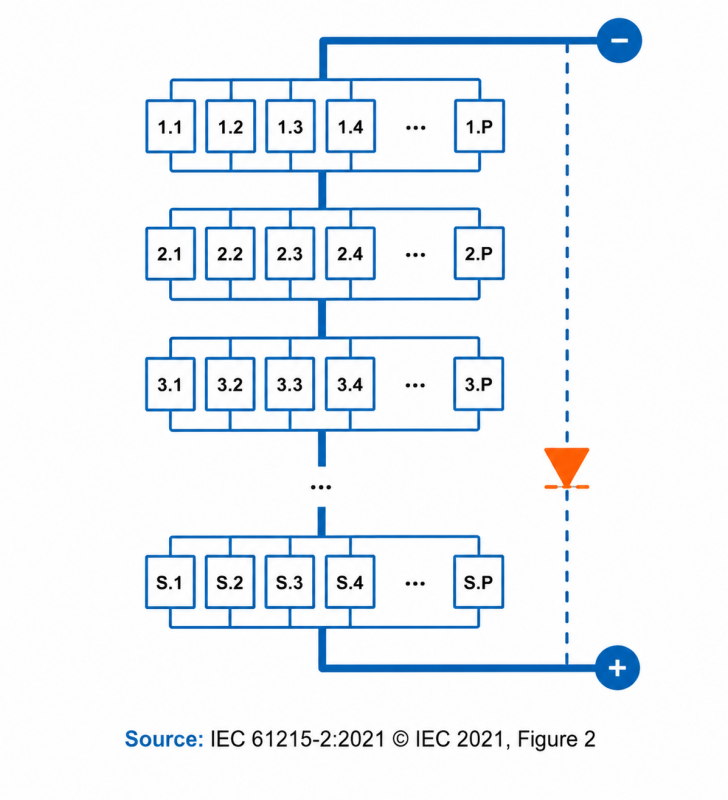
Case PS: Parallel-Series Connection
Parallel cell groups are connected within series blocks.

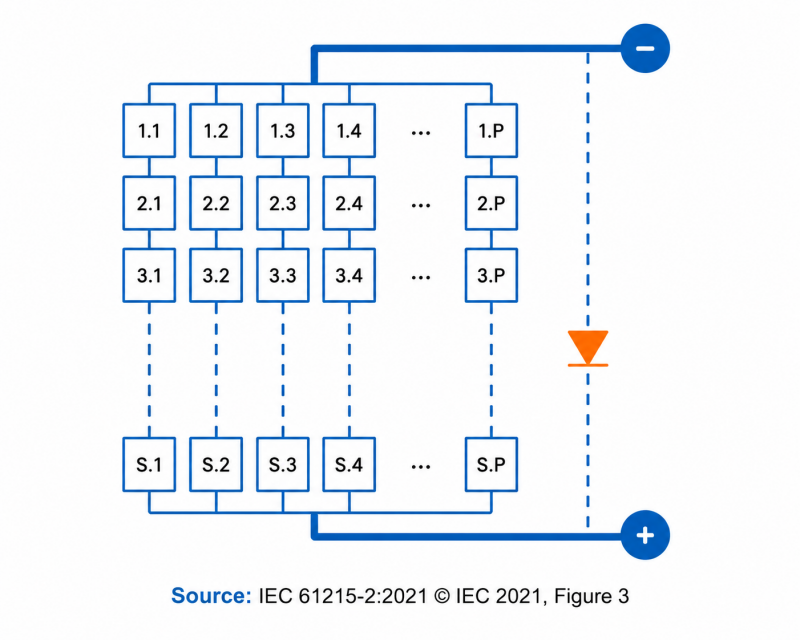
Case SP: Series-Parallel Connection
Multiple series strings are connected in parallel.

Each configuration requires a unique methodology to determine the most severe hot-spot condition.
Equipment Required for MQT 09 Testing
The IEC 61215 standard specifies the following equipment:
Radiant Source
Either:
• Natural sunlight, or
• A Class BBB (or better) steady-state solar simulator compliant with IEC 60904-9
Required irradiance:
1,000 ± 100 W/m²
For bifacial modules, additional requirements apply to front-side and rear-side irradiance control.
I-V Curve Tracer
Used to:
• Measure module electrical characteristics
• Identify sensitive cells
• Determine worst-case shading conditions
Current Measurement Equipment
Required for monitoring current through selected cell strings during testing.
Opaque Cell Masks
Used to create controlled shading conditions.
Infrared (IR) Camera
Required to:
• Monitor cell temperatures
• Identify hot-spot locations
• Record thermal behavior
Environmental Monitoring Equipment
Measures:
• Irradiance
• Integrated irradiance
• Ambient temperature
IEC 61215 MQT 09 Test Procedure
Step 1: Identify Hot-Spot Sensitive Cells
The process begins by exposing the module to irradiance between:
800 W/m² and 1,100 W/m²
The module's I-V characteristics are measured while individual cells are sequentially shaded.
The objective is to identify:
• Cells with the lowest shunt resistance
• Cells with the highest leakage current
• Cells most susceptible to reverse-bias heating
For bifacial modules, testing typically considers both front-side and rear-side illumination effects.
Step 2: Determine Worst-Case Shading Conditions
The next phase identifies the shading condition that produces maximum power dissipation.
Methods include:
Electrical Measurement Method
When cell circuits are accessible:
• Cell current is monitored directly.
• Shading is adjusted until maximum reverse-bias stress occurs.
I-V Curve Method
When cell circuits are inaccessible:
• Multiple I-V curves are collected under varying shading levels.
• The point where bypass diodes activate is analyzed.
• The worst-case hot-spot condition is determined.
Thermal Method
An alternative approach uses:
• Infrared imaging
• Progressive shading reduction
• Temperature monitoring
The highest measured cell temperature indicates the worst-case condition.
Step 3: Extended Hot-Spot Exposure
After identifying the most severe shading condition:
Monofacial Modules
The module is exposed to:
1,000 ± 100 W/m²
Bifacial Modules
Testing uses controlled bifacial irradiance conditions defined by IEC 61215.
Temperature Conditions
Module temperature:
55 ± 15°C
Exposure Duration
• Initial exposure: 1 hour
• Extended exposure: up to 5 hours if cell temperatures continue increasing
This stage simulates prolonged real-world shading events.
Special Procedures for Thin-Film Modules
Monolithically integrated (MLI) thin-film technologies such as:
• CdTe
• CIGS
• Amorphous silicon (a-Si)
follow MQT 09.2, a separate testing procedure.
Unlike crystalline silicon modules, thin-film modules often lack bypass diodes. As a result:
• Reverse voltage is not effectively limited.
• Groups of cells can enter reverse bias simultaneously.
• Different shading patterns must be evaluated.
The procedure identifies the number and location of shaded cells that produce maximum power dissipation.
Pass/Fail Criteria
After hot-spot testing, modules undergo additional qualification measurements, including:
• MQT 01: Visual Inspection
• MQT 02: Maximum Power Determination
• MQT 03: Insulation Test
• MQT 15: Wet Leakage Current Test
To pass MQT 09, the module must demonstrate:
No Major Visual Defects
Examples include:
• Melted solder
• Delamination
• Burn marks
• Severe enclosure damage
Functional Electrical Performance
The module must continue operating as a functional photovoltaic device.
Insulation Compliance
Insulation resistance must meet the same requirements as initial measurements.
Wet Leakage Current Compliance
Leakage current performance must remain within specification.
Any damage observed during the determination of worst-case shading conditions must be documented in the test report.
What MQT 09 Reveals About Module Quality
The hot-spot endurance test provides valuable insight into:
Cell Quality
Poorly manufactured cells often exhibit lower shunt resistance and higher susceptibility to reverse-bias heating.
Module Design
The effectiveness of:
• Cell layout
• String architecture
• Bypass diode placement
directly affects hot-spot behavior.
Module Design
The effectiveness of:
• Cell layout
• String architecture
• Bypass diode placement
directly affects hot-spot behavior.
Manufacturing Consistency
Modules with inconsistent cell performance are more likely to develop severe hot spots under shading.
Long-Term Reliability
A successful MQT 09 result demonstrates a module's ability to withstand realistic field conditions without catastrophic degradation.
Best Practices for Developers and EPCs
While IEC certification verifies baseline reliability, project stakeholders should perform additional due diligence.
Recommended actions include:
• Review IEC 61215 certification reports.
• Verify independent laboratory testing.
• Assess bypass diode design.
• Evaluate field performance history.
• Conduct factory quality audits.
• Analyze thermal imaging data during commissioning.
These measures help reduce the risk of hot-spot-related failures over a project's lifetime.
Conclusion
The IEC 61215 Hot-Spot Endurance Test (MQT 09) is one of the most important reliability assessments in PV module qualification. By simulating worst-case shading scenarios and prolonged reverse-bias stress, the test verifies whether a module can safely withstand hot-spot conditions without suffering significant electrical, thermal, or mechanical damage.
As solar projects increasingly target 25 to 35 year operational lifetimes, understanding hot-spot performance has become essential for manufacturers, investors, developers, EPCs, and asset owners. Modules that successfully pass MQT 09 demonstrate greater resilience against real-world shading events, helping ensure safer operation, higher energy yields, and reduced long-term maintenance risks.
However, certification alone does not guarantee long-term field performance. Access to verified test data, independent laboratory results, and comprehensive manufacturer quality assessments is critical when selecting PV modules for utility-scale, commercial, and residential projects.
Evaluate PV Modules with Confidence
Looking to compare solar module manufacturers, review reliability data, and access independent quality and bankability insights? Explore Sinovoltaics' Lab Advisor platform to make more informed procurement decisions and reduce project risk through transparent manufacturer and testing information:
By leveraging trusted quality assurance data alongside IEC certification results, stakeholders can build more reliable solar projects and improve long-term investment outcomes.
References
1. IEC 61215-2:2021 – Terrestrial Photovoltaic (PV) Modules – Design Qualification and Type Approval – Part 2: Test Procedures, Section 4.9 Hot-Spot Endurance Test (MQT 09).
2. IEC 60904-9 – Photovoltaic Devices – Solar Simulator Performance Requirements.
3. National Renewable Energy Laboratory (NREL) – PV Reliability Research.
4. International Energy Agency (IEA PVPS) – Photovoltaic Module Reliability Studies.