Albedo
Bypass Diodes
Solar Glazing
Single Phase Versus Three Phase Power Supply
Three phase power supply
Single Phase Power Supply
Module Measurement without Load
Module Measurement with Load
[...]

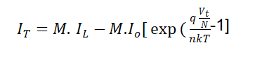 where:
N : number of cells in series
M : number of cells in parallel
IT : the total current from the circuit
VT : the total voltage from the circuit
I0 : the saturation current produced from a single solar cell
IL : the short circuit current from a single solar cell
n : the ideality factor of a single solar cell
q, k, and T : are constants.The total current is basically the individual cell’s current multiplied by the number of cells in parallel, while the total voltage is the individual cell’s voltage multiplied by the number of cells in series as below:ISC(total)=ISC(cell)×MIMP(total)=IMP(cell)×MVOC(total)=VOC(cell)×NVMP(total)=VMP(cell)×N
where:
N : number of cells in series
M : number of cells in parallel
IT : the total current from the circuit
VT : the total voltage from the circuit
I0 : the saturation current produced from a single solar cell
IL : the short circuit current from a single solar cell
n : the ideality factor of a single solar cell
q, k, and T : are constants.The total current is basically the individual cell’s current multiplied by the number of cells in parallel, while the total voltage is the individual cell’s voltage multiplied by the number of cells in series as below:ISC(total)=ISC(cell)×MIMP(total)=IMP(cell)×MVOC(total)=VOC(cell)×NVMP(total)=VMP(cell)×N